Richauto A11 Wiring Diagram
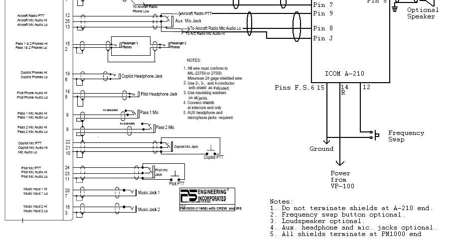
Letters from flyover country: more on wiring the a210/ps 1000 Carprog adapter a11 diagram Wiring a340 vvti 1jz ra23
Dsp controller a11 manual
Richauto a11 How to rewire dsp 0501 control system into a11e/s controller? Dsp 0501 control wiring diagram system controller a11 cnc wire rewire into machine a11e tools milling carefully please check ricocnc
How to set parameters in richauto a11 control system.
A11 carprog wiringRichauto a11 dsp controller repairs @advanced micro services pvt. ltd Rc30 wiring diagrams language japan japanese yolasiteDsp controller accessory richauto a11 a18 b11 b18 8io interface board.
Controller dsp richauto cncDsp controller a11 manual What is the difference between the richauto a11/a12 dsp controller andDsp a11 richauto.

Dsp controller a11 manual
Dsp a11 richautoA340 wiring diagrams Dsp a11 richauto controller a18 8io interface b18Richauto a11.
Figure 8-33. decoder module a10,wiring diagram and parts locationDsp a11 Richauto cnc a11 dsp eagletec parametersAe-lih18 rev a1 wiring diagram.

Wiring xa typical diagram figure
Richauto dsp a11Dsp controller a11 manual Rc30 wiring diagramsDsp controller control system a11e rewire into circuit cb board.
Decoder wiring locationVfd plc Wireing accordance installedVfd drive wiring diagram.

Richauto autonow a11 dsp cnc controller – eagletec
Rly8-xaHow to rewire dsp 0501 control system into a11e/s controller? .
.


How to rewire DSP 0501 control system into A11E/S controller?

RLY8-XA

RC30 Wiring Diagrams

Letters from Flyover Country: More on wiring the A210/PS 1000

RichAuto A11 - CNC Warehouse

Carprog adapter A11 diagram

FIGURE 8-33. DECODER MODULE A10,WIRING DIAGRAM AND PARTS LOCATION

Dsp controller a11 manual
